notes on assembling the Aerobie Rig
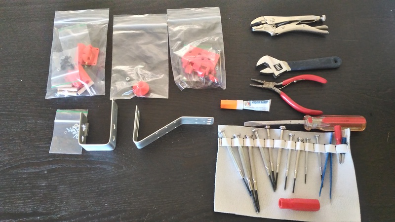
I purchased an Aerobee rig from the KAPtery because I’m real excited about the Jerk Pan mechanism. Our unpredictable late spring rains (its still spring in Oregon) have kept me from getting a good flight window to test this rig, but I hope to have it in the air soon.
I got an early version of the instructions and assembly. Overall, the assembly was straightforward and low-stress.
Issues
One sticking point was the leg brackets. the clearance for the screws forced me to jam them in at odd angles.
[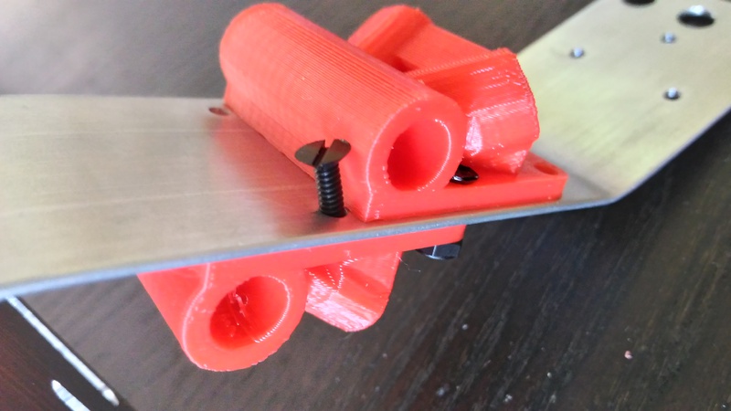
The plastic right under the leg attachment didn’t have enough clearance for a nut, and had to be trimmed with a knife:
[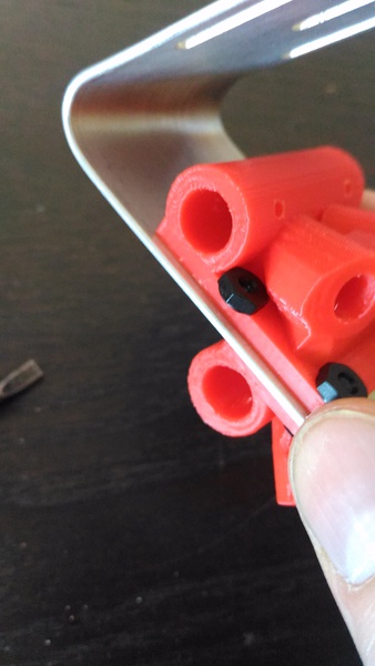
I’d suggest a change to the 3D printed file to get a little more clearance.
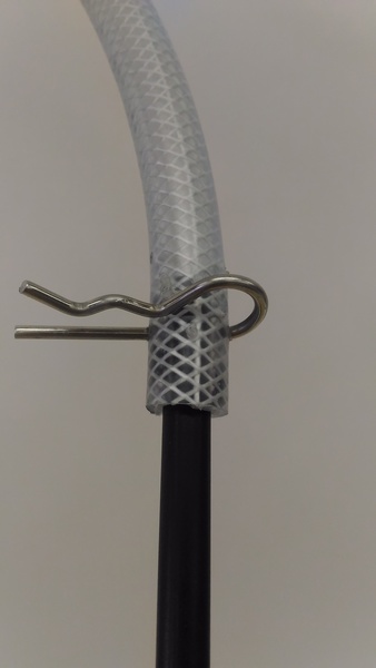
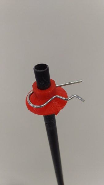
The hitch pins are almost impossible to get into the pendulum kit without stretching them open with pliers, then the kit easily assembles and disassembles:
[
[
Pendulum kit:
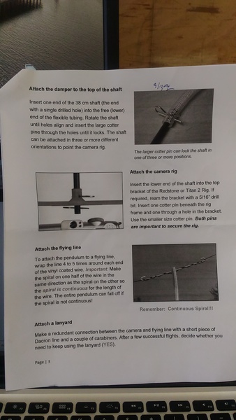
Some modifications to the pendulum kit are necessary to fit the jerkpan on the bottom. @cfastie may have already changed the instructions on this assembly.
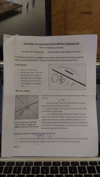
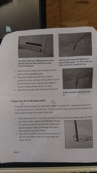
The instructions specify the need for a 5/64”, 5/16” drill bits. I used a 1/16”, 3/32”, 7/64, and 1/8”
they replace the current drill instructions in the following locations:
[
[
[
comments:
’’’ cfastie:
Thanks Mathew,
The holes in the aluminum frame for the leg brackets definitely needed modification. I make them bigger now and moved some of them about 1 mm. Some are still a tight fit, but the screws will fit if you bother them enough. Your Aerobee was shipped before I recognized that problem.
The leg brackets have always had that problem that the nuts won’t fit back into that crevice far enough. You got a new version of the brackets where I tried to fix that, but there is still not enough room. The instructions for other KAPtery rigs suggest slicing two of the corners off the nylon hex nut, but recently I have been using the Dremel to widen the crevice before I ship them. Before I print another batch of those I will modify the model, although the cruft in that old model makes it hard to work with. Maybe I need Ranon and Fusion 360!
It’s really good for me to see what you did with the cotter pins. It’s certainly hard to work those in sometimes, but I have never bent one open to make it easier. I just drill the holes larger (and aligned) until the pin slides in. Bending the cotter pin makes it less secure (more likely to slip out – they are designed to “lock” in that middle bend), so I should make sure people don’t do that. The system requires that the holes be just the right size (if they are too big it weakens the suspension shaft). If I could think of a different way of attaching the shaft I would consider it, but it has to be an absolutely secure attachment because the entire rig falls off if it fails.
You’re right about the drill bit sizes. I will rework those instructions. The listed bit sizes are probably the ones I used, but a small bit can quickly make a big hole in that fiberglass shaft, so some of the bits I listed are smaller than the hole should be. I should be more explicit about that, but I should also avoid making the instructions more tedious than they already are. It’s a challenge to find the proper compromise.
Thanks for the feedback. I wish more people would share their experiences.
Chris ‘’’
Archived 4th of March 2018 from Publiclab.org.